In system designing, sometimes it is necessary to connect power supplies (PSUs) in parallel to obtain higher power greater than available from one power supply and/or to provide system redundancy. In the following article, we will explain the types of parallel connections that can be used for increasing power and setting up redundancy systems.
Types of Paralleling
Direct Connection Method
A seemingly simple method would be to connect the power supplies directly together without any user set up intervention. In practice, due to small parametric differences between the power supplies, one power supply will have a slightly higher output voltage and will try to deliver the full load current and possibly go into current limit – potentially shutting down. Thermal issues can also occur, resulting in shortened lifetime. The next power supply would then follow a similar sequence.
Some PSUs can be set up to share to a reasonable level, but manufacturers specifications should be checked to ensure suitability.
This method is the least desirable because accurate current balancing cannot be achieved and it is difficult to set up and maintain stability. The following considerations should be applied for this method.
- Use identical power supplies that will have closely matching characteristics.
- Select units with a constant current limit feature. Foldback, hiccup or latching current limit characteristics can lead to glitching and /or shutdown.
- Adjust the output voltage of each power supply to be as close as possible (within a few mV). Choose power supplies with multi-turn adjustment potentiometers – a single turn potentiometer may not have sufficient resolution and precision required.
- The length and gauge of each supply wire connected to a load must be the same as possible. Do not daisy chain the connections.
- The voltage setting accuracy can drift with temperature over time. The power supplies should be located together so that temperature differences are minimized.
- It is recommended to operate the power supplies with a maximum total output power < (N × 80% × rated power). For example, if 2 units of 120W PSUs are connected in parallel, then the recommended total output power should be (2x120W)*0.8=192W.
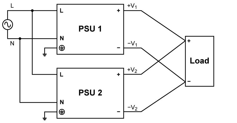
Fig-1. Direct Connection Method (1+1)
Passive or active current sharing are the preferred techniques that can be used to achieve balanced loading between power supplies for both higher power and redundant applications.
- Passive Current Share
- Active Current Share
Droop mode (passive mode) sharing is a simple pragmatic method which can be used in applications that can tolerate some degradation of voltage regulation compared to a single power supply. Typically, these will be 12V, 24V, 48V units powering loads such as motors, relays, solenoids, PLCs and DC-DC converters.
Lower voltage applications e.g., 3V and 5V powering logic circuits may not tolerate the level of voltage regulation in droop mode and would be more suited to Active Current Sharing.
Certain manufacturers offer products with droop capability specified which can be enabled by a selector switch or jumper connection.
In droop mode the power supply has an internal voltage drop enabled which causes the output voltage to drop (droop) with increasing current. The amount of voltage drop will vary according to the specific models selected but will typically be in the range of 2.5% to 5% from zero to full load.
The output voltage setting of each power supply should be adjusted under zero load to match as closely as possible. In practice one unit will always be slightly higher and this will start to deliver the load current until the voltage drops to match that of the second unit, which will then start to share the loading.
For optimum performance, the caveats of identical unit selection, precise voltage setting, equal length wiring and unit temperatures as highlighted in the Direct Connection section above should be observed. Sharing accuracy in the range of 60:40 or better can be achieved.
This technique uses a connected internal control circuit (with current share wire), which ensures the exact output voltage synchronization of each power supply, and the load is equally shared. Long cable lengths should be avoided to prevent the risk of interference occurring with the current sharing function.
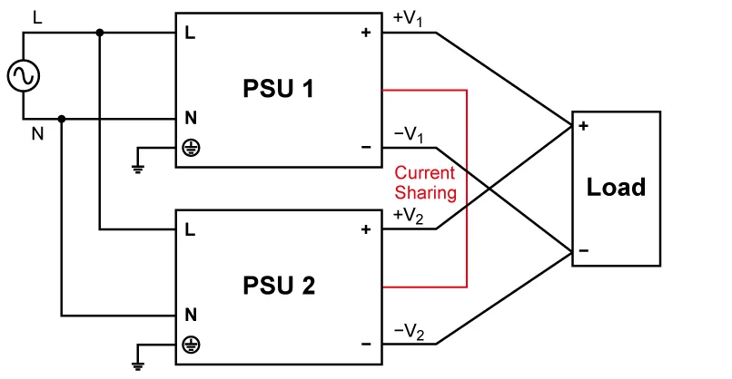
Fig-2: Active Current Sharing (1+1)
System Redundancy
The idea of redundant operation is to utilize more PSUs to power the same load, so that in case of one PSU failure the total load is able to shift onto other PSUs for continuous power delivery. This method is utilized for applications where system uptime is critical. For true redundancy, each power supply should have separate AC feeds or a back up system using batteries or a generator for example.
For redundant operation, PSUs must be isolated through ORing diodes/FETs or redundancy modules. This will ensure protection against reverse current flow in the event of an output failure in one of the power supplies. Various PSU types can be selected depending upon the end system integration requirements. Active or passive current sharing can be deployed according to the PSU model chosen.
Hot swap (pluggable) power supplies contain an internal ORing diode or MOSFET, thus simplifying system integration and replacement of faulty PSUs.
Certain Embedded (chassis mount) power supply ranges are offered by some manufacturers with an internal diode/MOSFET but PSUs without this feature can also be used by adding external diodes or MOSFETs-which require an additional external control circuit. Proprietary ICs are available to simplify implementation. This circuit, however, becomes a single point of failure.
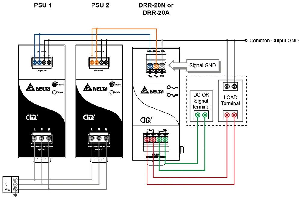
Fig-3: With Redundancy Module (1+1)
Based on the application, redundant mode can be (1+1) or (N+1) type.
Choose Schottky diodes to minimize power losses because these have a lower forward voltage drop (typically 0.15 - 0.45V) compared to standard silicon diodes (0.7V).The voltage drop increases with temperature so good thermal management by heatsinking will be necessary. To ensure a manageable device temperature rise ,and also to enhance reliability, the ORing diode current rating should be at least 2x output load current and reverse voltage rating should be 2x PSU output voltage.
For higher current applications, the power losses with diodes may be unacceptable. An alternative solution is to use MOSFETS configured for use as a near ideal diode which have a much lower forward voltage drop and hence significantly less power dissipation. Suitable driver ICs are commonly available.
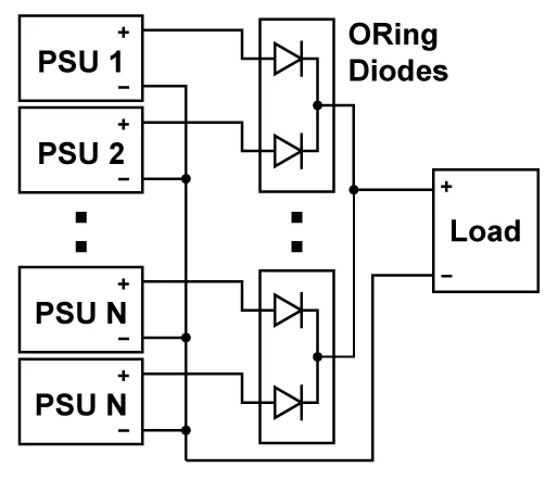
Fig-4: With ORing Diodes (N+1)
Delta Standard Power Supplies That Support Active Current Sharing
| MEB Series Enclosed Power Supplies for Industrial and Medical Use | IMA PLUS Series Enclosed Power Supplies for Industrial and Medical Use |
|
|
|
|

For local purchase and service of industrial and medical power supplies, please contact our authorized distributors at https://deltapsu.com/en/contact/find-a-distributor.